SF6 Recovery Unit Sizing Guide for 110kV GIS Substations | Operational Efficiency
Managing sulfur hexafluoride (SF6) gas in high-voltage Gas Insulated Switchgear (GIS) substations requires a precise balance between operational uptime, environmental compliance, and capital investment. For a standard 110kV GIS substation powering an urban center, selecting the right SF6 gas recovery unit is an essential technical and financial decision.
Equipping grid operators with properly sized recovery systems ensures swift turnaround times during maintenance while meeting global emissions targets.
1. Substation Gas Inventory Profile
A typical 110kV urban GIS substation supplying electricity to 100,000–250,000 residents generally features a 6 to 10 bay layout (including transformer bays, line bays, and bus couplers).
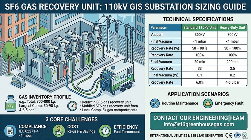
Total SF6 Gas Inventory: 300 kg to 800 kg across all gas compartments.
Largest Single Compartment: 50 kg to 90 kg (typically the main busbar or circuit breaker chamber).
Rated Operating Pressure: 0.40 MPa to 0.65 MPa (4.0 to 6.5 bar positive pressure).
To avoid extended outages during scheduled maintenance or emergency intervention, recovery systems must balance vacuum pump capacity, compressor displacement, and storage volume.
Engineering Tip: If you are sizing equipment for a specific substation layout or expanding existing gas management fleets, contact our engineering team at [email protected] for a customized on-site capacity assessment and technical recommendation.
2. Industry Pain Points: Compliance, Cost, and Efficiency
Substation asset managers face three primary operational challenges:
                  ┌────────────────────────────────────────┐
                  │   3 Core Gas Management Challenges     │
                  └───────────────────┬────────────────────┘
                                      │
         ┌────────────────────────────┼────────────────────────────┐
         ▼                            ▼                            ▼
┌─────────────────┐          ┌─────────────────┐          ┌─────────────────┐
│   COMPLIANCE    │          │      COST       │          │   EFFICIENCY    │
│ Recovery <1 mbar│          │ High SF6 Costs  │          │ Fast Turnaround │
│  (IEC 62271-4)  │          │ Purify & Reuse  │          │  Min Downtime   │
└─────────────────┘          └─────────────────┘          └─────────────────┘
Regulatory Compliance: International standards such as IEC 62271-4 and updated environmental mandates (including EU F-Gas regulations) restrict atmospheric emissions and mandate gas recovery down to less than 1 mbar residual pressure.
SF6 Supply Costs: With raw gas prices fluctuating and supply tightening, purifying and re-using existing gas on-site yields substantial savings compared to buying virgin SF6 and paying disposal fees.
Outage Minimization: Every hour a 110kV feeder remains de-energized risks grid stability. Equipment with inadequate pumping speeds extends labor hours and inflates maintenance costs.
3. Recommended Technical Specifications Matrix
To achieve complete gas extraction within a standard 1 to 2-hour maintenance window per compartment, a mobile SF6 gas recovery unit with a vacuum capacity of 30 m³/h to 55 m³/h and oil-free high-pressure liquefaction technology is recommended.
| Specification Parameter | Standard 110kV Unit | Heavy-Duty Multi-Bay Unit |
| Substation Suitability | 110kV GIS (6–8 Bays) | 110kV–220kV GIS (10+ Bays) |
| Vacuum Pump Displacement | 30–40 m³/h | 55–80 m³/h |
| Final Recovery Vacuum | ≤ 1 mbar (≤ 0.1 kPa) | ≤ 0.1 mbar (≤ 0.01 kPa) |
| SF6 Recovery Efficiency | ≥ 99.9% | ≥ 99.95% |
| Compressor Type | Oil-free, dry-running reciprocating | Oil-free high-pressure compressor |
| Liquefaction Capacity | 25–35 kg/h | 50–70 kg/h |
| Purification System | Particle filter (0.1 µm) & molecular sieve | Dual-stage drying & acid absorption |
| Integrated Storage | 100–300 L on-board tank | External storage bottle rack integration |
4. Key Application Scenarios
Routine Maintenance & Overhauls
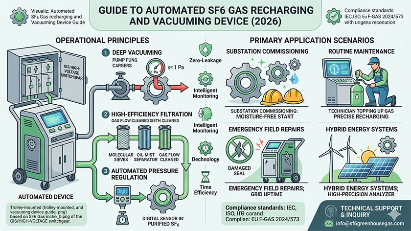
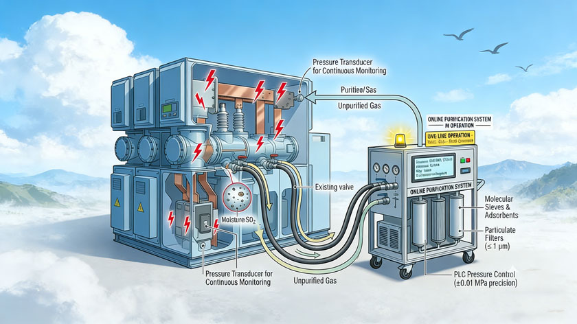
During 5-year or 10-year major maintenance cycles, circuit breaker chambers must be fully evacuated. The recovery unit extracts the gas, removes decomposition byproducts (such as SO2 and HF), dries moisture content to below 50 ppm, and stores the gas as a liquid under pressure.
Emergency Fault Handling
In the event of an internal arc fault, the recovery unit safely draws out contaminated gas through acid-neutralizing filters, ensuring safe working conditions for maintenance personnel before opening switchgear enclosures.
Need technical advice? Send your switchgear layout or compartment gas volumes to [email protected] to receive one-on-one engineering guidance and tailored equipment selection parameters.
5. Procurement Buying Guide for International Utilities
When evaluating an SF6 gas recovery unit, utility procurement teams should prioritize the following verification steps:
Oil-Free Compressor Architecture: Eliminates oil contamination during compression, preserving dielectric strength for immediate gas re-injection.
Deep Vacuum Capability (≤ 1 mbar): Prevents micro-quantities of gas from escaping to the atmosphere during evacuation.
Rugged Mobility & Protection: Industrial pneumatic wheels and IP54-rated enclosures allow smooth navigation across gravel yards and indoor substation basements.
Compliance Certification: Ensure equipment carries relevant CE, ISO 9001, ISO 14001, and ASME/PED pressure vessel certifications.
6. Frequently Asked Questions
What capacity recovery unit is required for a 110kV GIS compartment?
A recovery unit offering a 30 to 40 m³/h vacuum pump displacement and a 25 to 35 kg/h liquefaction speed can recover a standard 60 kg compartment down to 1 mbar in under 2 hours.
Can recovered SF6 gas be recharged directly back into GIS switchgear?
Yes. Integrated particulate filters, dry molecular sieves, and acid filters restore used gas to IEC 60480 re-use standards (moisture < 50 ppm, purity > 98%), making it suitable for immediate recharge.
Why is an oil-free compressor mandatory for SF6 handling?
Standard oil-lubricated compressors release oil vapor into the gas stream. This vapor degrades the insulation properties of SF6 and contaminates internal switchgear contacts. Dry-running, oil-free compressors prevent cross-contamination.
Request a Technical Proposal: For pricing, specifications, or to schedule a free technical consultation on SF6 handling systems, email our engineering specialists at [email protected].
Leave A Message
Your email address will not be published. Required fields are marked *
More Articles