What Are the Steps to Use SF6 Handling Equipment for Gas Recovery? A Compliant Guide
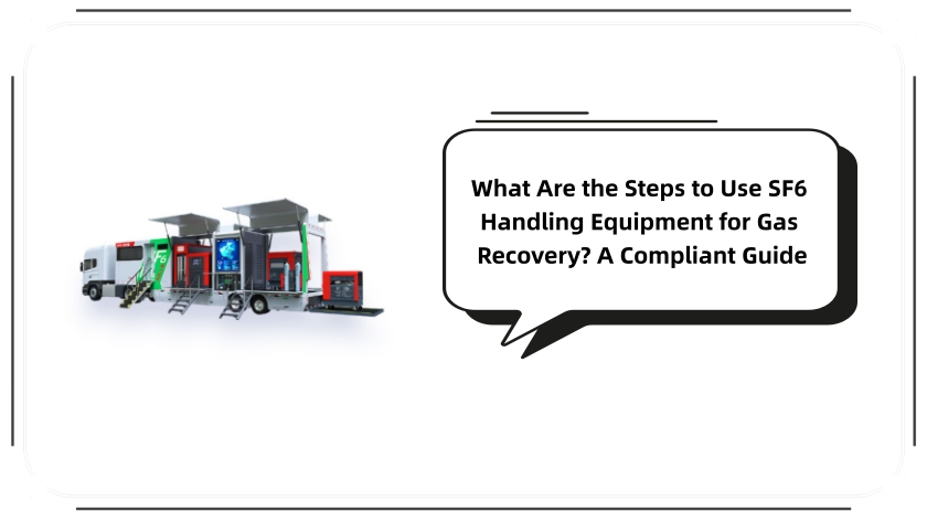
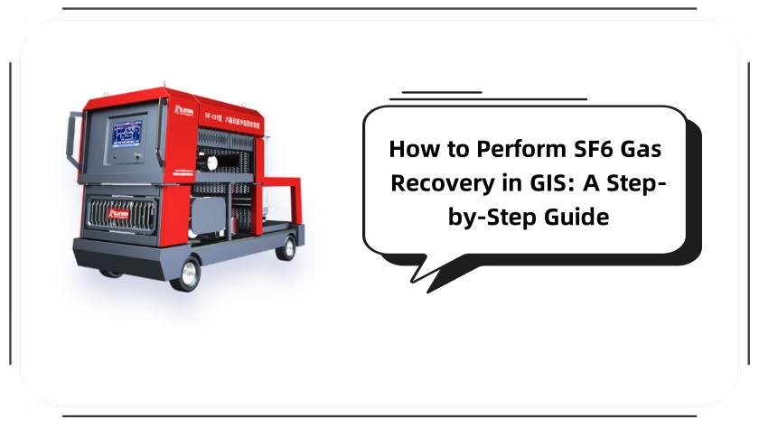
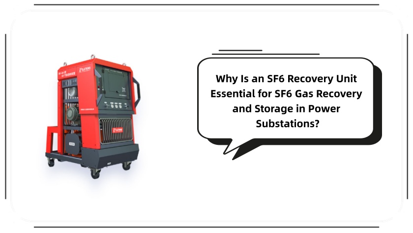
SF6 (sulfur hexafluoride) is a critical insulation gas in high-voltage electrical systems—yet its global warming potential (GWP) is 23,500 times that of CO₂ (IPCC 2022 Report). For utilities, manufacturers, and maintenance teams, mastering the steps to use SF6 handling equipment for gas recovery isn’t just an operational task: it’s mandatory for meeting regulations like EPA 40 CFR Part 82 (U.S.) or IEC 60480 (global), which require ≥95% SF6 recovery efficiency. This guide breaks down the process with safety, compliance, and efficiency at its core—answering exactly “What are the steps to use SF6 handling equipment for gas recovery?” for both novice and experienced operators.
Step 1: Pre-Inspection of SF6 Handling Equipment (Critical for Leak Prevention)
Before powering on any tools, a rigorous pre-inspection ensures your SF6 handling equipment performs optimally and avoids costly gas leaks. This step aligns with ISO 14535, the global standard for SF6 gas handling.
Check structural integrity: Examine the recovery unit’s casing, pressure hoses (replace if kinked or cracked), and quick-connect fittings. For O-rings, use only fluor rubber seals—standard rubber degrades in SF6 and causes leaks.
Calibrate instruments: Verify pressure gauges (range: 0–25 MPa) and vacuum meters (accuracy: ±0.1 Pa) against a certified reference. Faulty gauges lead to under-recovery or overpressurization of storage cylinders.
Prepare consumables: Replace filter elements if they’re discolored (indicates moisture/impurity buildup). Ensure the SF6 storage cylinder is DOT 3AA-certified (U.S.) or GB 5099-compliant (China), with a valid hydrostatic test sticker (expires every 5 years).
Step 2: Safety Preparation for SF6 Handling Equipment Operation
SF6 is non-toxic but displaces oxygen—posing asphyxiation risks in confined spaces. This step is non-negotiable for OSHA (U.S.) or EU-OSHA compliance.
Wear PPE tailored to SF6 tasks: Chemical-resistant gloves (nitrile or neoprene), impact-resistant safety goggles, and a NIOSH-approved respiratory mask (if ventilation is poor). For confined spaces (e.g., substation vaults), use a portable oxygen monitor to maintain ≥19.5% O₂ levels.
Optimize workspace ventilation: Use axial fans (airflow ≥5 m³/min) to circulate air. Keep the area 10+ meters away from open flames—SF6 decomposes at 300°C into toxic SO₂ and HF.
Review regulatory checklists: For U.S. operators, confirm compliance with EPA’s “Significant New Alternatives Policy (SNAP)” for SF6 recovery. For EU teams, align with REACH Regulation (Annex XVII) limits on SF6 emissions (<0.1% of recovered volume).
Step 3: Connect SF6 Handling Equipment to the Target Device
Poor connections cause 40% of SF6 recovery failures (per IEEE Trans. Power Delivery, 2023). Follow these steps for a secure, leak-free link:
Depressurize safely: If the electrical device (e.g., circuit breaker, GIS) has a pressure ≥0.3 MPa, slowly open its relief valve until pressure drops to 0.1–0.2 MPa. Never connect to high-pressure devices—this can burst hoses.
Clean and secure fittings: Wipe the device’s gas outlet and equipment’s inlet with isopropyl alcohol (to remove oil/debris). Align the male/female connectors and tighten with a torque wrench (30–40 N·m for stainless steel fittings—over-tightening strips threads).
Test for leaks: Use a portable SF6 leak detector (sensitivity: ≤1 ppm/v). Apply a soapy water solution to joints—bubbles indicate leaks. For persistent leaks, replace the fitting’s backup ring (use PTFE material for SF6 compatibility).
Step 4: Evacuate the Recovery System (Vacuuming for Purity)
Air and moisture contaminate SF6—reducing its insulation performance and corroding equipment. IEC 60480 mandates a vacuum level ≤5 Pa for the recovery system.
Close all valves first: Ensure the recovery unit’s inlet/outlet valves, storage cylinder valve, and vacuum pump valve are fully closed.
Run the vacuum pump: For stationary SF6 handling equipment, use a dual-stage rotary vane pump (flow rate ≥20 m³/h). For mobile units, confirm the pump’s oil level is between the “MIN” and “MAX” marks. Run the pump until the vacuum meter reads ≤5 Pa.
Hold and verify vacuum: Close the pump valve and wait 10 minutes. If the vacuum rises above 10 Pa, check for leaks (focus on hose connections or the storage cylinder’s valve seat).
Step 5: Initiate SF6 Gas Recovery (Control Flow & Temperature)
This is the core step to use SF6 handling equipment for gas recovery—precision here ensures high efficiency and equipment longevity.
Adjust valve openings slowly: Open the target device’s gas valve ¼ turn first, then the recovery unit’s inlet valve. Use the flow control knob to set a rate of 0.5–1 m³/h (rapid flow causes pressure spikes).
Monitor key parameters: Track the recovery unit’s temperature (keep ≤50°C—use the built-in cooling fan if it exceeds 45°C). The storage cylinder’s pressure should not exceed its rated limit (typically 15 MPa for 40L cylinders).
Maximize recovery efficiency: When the target device’s pressure drops to 0.02 MPa, switch the recovery unit to “booster mode” (if available) to extract residual SF6. This ensures compliance with IEC 60480’s 95% recovery requirement.
Step 6: Post-Recovery Purge & Disconnection
Even small amounts of residual SF6 cause emissions—this step minimizes waste and protects equipment.
Purge the system with dry nitrogen: Close the target device’s valve, then open the recovery unit’s purge valve. Inject dry nitrogen (dew point ≤-40°C) at 0.2 MPa to flush hoses and the unit. Collect the nitrogen-SF6 mixture in the storage cylinder.
Depressurize and disconnect: Open the recovery unit’s relief valve to release residual pressure (≤0.01 MPa). Cap the target device’s gas outlet and the equipment’s inlet to prevent contamination.
Inspect hoses post-use: Check for bulges or softening (signs of overpressurization). Coil hoses neatly to avoid kinking.
Step 7: Shutdown, Maintenance & Documentation
Proper follow-up extends your SF6 handling equipment’s lifespan and simplifies regulatory audits.
Shut down equipment in order: Turn off the recovery unit first, then the vacuum pump. Disconnect the power cord and wipe the unit’s exterior with a damp cloth.
Perform maintenance tasks: Replace the recovery unit’s moisture filter (every 50 hours of use) and the vacuum pump’s oil (every 100 hours). Lubricate valve stems with SF6-compatible grease (e.g., Dow Corning Molykote 55 O).
Document the operation: Log details per EPA and IEC requirements:
Date/time, operator name, and target device ID
SF6 recovered (calculate via PVT formula: V = (P×V_cylinder)/(R×T))
Vacuum levels, temperature peaks, and any issues (e.g., leaks fixed)
Conclusion: Mastering the Steps to Use SF6 Handling Equipment for Gas Recovery
By following these steps, you ensure safe, compliant, and efficient SF6 recovery—protecting the environment from potent greenhouse gas emissions and extending your electrical equipment’s life. Remember: always refer to your SF6 handling equipment’s user manual (e.g., models from Siemens, Hitachi, or local suppliers) for model-specific adjustments. For further guidance on SF6 purification or storage, refer to ISO 14535 or consult a certified SF6 service provider.
Leave A Message
Your email address will not be published. Required fields are marked *

